sábado, 23 de septiembre de 2017

What is Punching Shear?

What is Punching Shear?

The punching shear is a failure mechanism in structural members like slabs and foundation by shear under the action of concentrated loads.
The action of concentrated loads is on a smaller area in the structural members. In most cases, this reaction is the one from the column acting against the slab.
The punching shear failure mechanism is observed in normal floor slabs, flat slabs, and in the foundation slabs below the column.

Punching Shear in Reinforced Concrete Slabs

The Punching shear in reinforced concrete slabs can be considered as a 2D analog of the shear observed in beams. This kind of failure occurs as a sudden rupture. This rupture cannot be restrained by the help of main reinforcement.
Hence, there is a reduction of ultimate load capacity of the structure below the flexural capacity by the action of shear. But when compared to beam shear, the punching shear is less critical.
In slabs, the punching shear occurs when they are subjected to high values of concentrated loads. These load categories includes the wheel loads on the bridge slabs or the loads from above floors on the columns that support the slab floors.

Calculations in Punching Shear

The calculations of punching shear dealt in the design is based on the punching shear force that is punching against the thickness of the slab or foundation. This can happen only if there exists shear alone in the system. This is not possible if there exist any form of moment in the pedestal or the column.
The Maximum Punching Shear Stress is determined based on the punching shear failure cone and the applied values of shear and moments.
Punching Shear Failure Zone for Slabs
Fig.1. Punching Shear Failure Zone for Slabs above and below the column
The ‘d’ is the effective depth of the slab. The punching shear perimeter is formed at a distance of d/2 from the edges of the column or the pedestal. In the figure-1, Dped is the depth of the pedestal.

Design Considerations for Punching Shear in Slabs

The Punching Failure in the structure can be prevented by taking the following control measures:
  1. Undergo proper checking to make sure that the concrete itself is strong enough.
  2. If the concrete lacks adequate strength, check whether the amount of reinforcement that is provided is reasonable.
  3. If it is not reasonable, it is recommended to change the form of the structure.
The methods involved in changing the form of the structure are:
  1. Increasing the depth of the slab
  2. The column size can be made larger
  3. Incorporation of drop panels
  4. Introduction of Flared column heads
  5. Other foreign codes can be referred to practice other liberal designs
Different failure zones are mentioned below in figure-2 based along with the area where the reinforcement have to be provided. Usually vertical and traverse failure lines are possible. We do not actually know where the failure can occur. So, each possible failure plane must be reinforced.
Punching Shear Failure Zones
Fig.2: Punching Shear Failure Zones
Based on building codes, the slabs are designed for punching shear as follows:
1. A cylindrical control surface is considered around the loaded area or the column area at a particular distance. This distance is proportional to the slab depth. This is shown in figure-3.
Control Surface Under Punching Failure
Fig.3. Control Surface Under Punching Failure – Notation and Definition
2. The average shear stress on the control surface must not exceed the design strength. This design strength is often proportional to the tensile strength.
The effects of moment transfer at the column or the slab junction is facilitated by the design for punching shear. The punching shear assessment is based on different parameters. These parameters are sections at particular distance from the face of the column.
Among different sections, the most important ones are at the face of the column and at a distance of d/2 on either side of the column.
If the shear stress at these sections exceeds the allowable stress value, the structure will be subjected to punching failure. The design formulas and parameter distance would vary from one code to other. But the concept behind the assessment of punching shear failure is the same.

by : www.theconstructor.org

domingo, 26 de marzo de 2017

PERFORMANCE BASED EARTHQUAKE RESISTANT DESIGN

The performance-based seismic engineering (PBSE) produces structures with predictable seismic performance. This approach is not new. Using this approach / model Turbine, Airplanes & Automobiles are made. In these applications one or more prototype are built and subjected to extensive testing. To incorporate the lessons learned from the experimental evaluations the design and manufacturing process is then revised, once the cycle of design, prototype manufacturing, testing and redesign is successfully completed, the product is manufactured in a massive scale.
In the automotive industry, for example, millions of automobiles which are virtually identical in their mechanical characteristics are produced following each performance-based design exercise.
Performance Based Earthquake Engineering/Design is not that popular because the scale of output is not large in comparison to the Automobile industry and others. Each building designed by this process is virtually unique and the experience obtained is not directly transferable to buildings of other types, sizes, and performance objectives. Therefore, up to now PBSE has not been an economically feasible alternative to conventional prescriptive code design practices. In coming few years we can say that Performance Based Design will become the standard method of delivering Earth Quake resistant designs.
The facts are clear – We cannot prevent big, destructive earthquakes from occurring. These pose a continuing threat to lives and property in more than 55% of the area of this country. However, it is possible to avoid the disastrous consequences of an earthquake and that precisely is the objective of every seismic design code practice.
The seismic codes are framed primarily with the objective of prevention of loss of life. In order to meet this objective it is essential that the structures/constructed facilities respond to the expected earthquake ground motions at the site in a designated manner, which in turn depends on the nature of ground motion exciting the structure.

image
Thus the reliability of achieving the life safety performance objective of any constructed facility is governed by the most uncertain element in the chain- expected ground motion.
Seismic hazard and Damage state are the two essential parts of a Performance objective. Seismic performance is described by designating the maximum allowable damage state (performance level) for an identified seismic hazard (earthquake ground motion). The target Performance level is split into two levels Non-structural damage and Structural damage, the combination of the two gives the building a combined performance level.

sábado, 25 de febrero de 2017

Earthquake vs Energy Dissipation

In this blog post, I will try to explain in simplest words possible as to what happens to a building during an earthquake. 

Imagine this: You are travelling in a car which I am driving. I applied a sudden brake. You will experience a serious "jerk" and most probably curse me after that. But that sudden "jerk" also called as deceleration is experienced because your body changed the velocity from 100 feet/second to dead zero in 3 seconds. That is equivalent to gravitational acceleration applied in horizontal direction. This is called inertial force. There was a change in state of motion of your body. 

"A body at rest stays at rest and a body in motion stays in motion unless an external force is applied to change the state of body" - Newton's first law of motion. 

A force experienced by a body is equal to:

Force = Mass x Acceleration

When earth shakes, it gives these impulses at the base of the building. Let us look at an acceleration time history. (A record showing the ground acceleration plotted against time)


You can see how violently a ground shakes. It forces the building base to move along with it. So if you are staying in basement during an earthquake, you will experience a similar violent acceleration which may throw you anywhere. This ground acceleration that excites the building is in a way pumping energy into the building. This energy increases with time as the ground is shaking. But in the zone of strong excitation this energy increases quite drastically. A graph of seismic energy will look something similar to this:

The bottom two graphs in above image shows the intensity of earthquakes (Arias Intensity) and the region in which there is a steep slope defines the region of strong shaking. Now if the building that you have designed is not able to handle this steep energy curve, that is if it cannot handle the rate seismic energy entering into the building, then it will collapse. But we know that we cannot design a building to store this much amount of energy, so we have to design it in such a way that it dissipates this energy entering into the building. But the major question is how can we dissipate energy from the building?

Before moving to energy dissipation, let us talk about how a force can be looked as energy absorbed into the system. Whenever a force acts on an object, the force deforms that particular object which means that object experiences different strains. This force times the amount of deformation is called strain energy. Similarly if building dissipates energy between two oscillations, it is called damping energy and so on. So during an earthquake motion, seismic energy is entering into the building system and the this energy that is entered is dissipated from the building in terms of inelastic deformations, elastic deformations and damping.

Seismic Energy = Inelastic energy + Strain Energy + Modal Damping + Rayleigh Damping + Additional Viscous Dampers

Let us talk about all these energies and focus on the most critical part of the above equation. 

1. Strain Energy

Strain energy is the elastic deformation energy. This means that the elements in the building will stay elastic and deform within the elastic zone. The principle of superposition will be applicable and stress will be proportional to strain. But the amount of earthquake energy dissipated by this energy is very less. If you are thinking why, then here is the answer. As I said that the strain energy is just the elastic zone of the members experiencing lateral forces, the energy will be 1/2*Force*Deformation. Now even if the members each the yield capacity the elastic deformations at that yield capacities are very low. Take a look at graph below:

Area under the curve: Elastic strains and plastic strains


As you can see from the image above, that the elastic strain energy zone is very small. That is it starts from 1 and reaches up to point 2. Thus the area under that curve is the energy absorbed by member. This is the reason why even if we have so many members but the the strain energy dissipation during earthquakes is so low as compared to other energy dissipation.

2. Damping Energy

As discussed in our previous blog Response Spectrum Analysis, we talked about damping. Damping is the energy released from the system. Take a tuning fork or a scale in your hand, hold it tight and give it an impact. At the beginning of the impact the scale will start oscillating violently, but soon the vibrations will lower down and eventually come to stop. Now one might wonder where did all the energy go? Because the total input energy should be equal to the total output energy. So over here, majority of the energy dissipated in the form of damping energy. How can I say that? Well, when you gave a hit to the scale as soon as it started oscillating, your hand started shaking as well as the bond between you hand and the scale was not entirely rigid. So the scale started losing most of its energy at the scale-hand interaction. Apart from this your hand also started shaking which results in some more energy dissipation.

Figure showing undamped oscillation

Damping is a kind of black hole for structural engineering. We know that the faster a building oscillates, the faster it will dissipate energy as damping energy released is directly proportional to the velocity of object moving. But we don't know how much amount of damping coefficient each building can provide. It can range from 1.5% for tall buildings to 5% for short concrete buildings. So a shorter building can quickly dissipate its energy as compared to a taller building. A tall building goes under many free oscillations after an earthquake ends while a shorter building stops oscillating quite quickly as soon as the earthquake ends. Just because a taller building has lower damping coefficient and they have longer periods. A tall building can have a period ranging from 4 seconds to as high as 10 seconds. While a short building has a period of less than 1 second. Now how does it matter? Damping energy is released within each cycle.

Figure showing damped oscillation describing energy loss in every cycle

let us say you are measuring energy released from the building in 20 seconds. The two building that we are placing under the microscope has the same damping constant but different periods, one has a period of 1 second while the other has a period of 5 seconds. Now the building with a period of 1 second will oscillate 20 times while the building with 5 second period will oscillate 4 times. Now let us say the energy released is 5% in each cycle of the total energy in building. Then definitely the building with more cycles will release energy more quickly. Of course there are many different parameters into consideration but this the simplest way I can explain as how come a shorter building stops vibrating more quickly as compared to a tall building.

The damping energy that is released is in for of cracking of concrete or banging of two members against each other, banging of wall against a structural member and what not. We will go into the details of damping into another article.

3. Additional Viscous Dampers

Sometimes when the building is too sensitive to small forces say for example wind, then we install additional dampers to attain higher amount of damping. This damping absorbs a lot of energy from the structure. You can tune the damping as per your wish say 2% or 3% or even 5% additional to what the building can provide. These are dashpots that are installed in the form of a brace or as a link between the beam.

Viscous dampers installed in a building in diagonal action

These dampers have critical damping coefficient and the maximum force that they can resist. Any additional force will not be resisted it will end up deforming more than specified. So it becomes critical as how you model these dampers. Generally in case of modelling you should assign a spring and a damper in series where spring will reflect the stiffness of the member and damper will reflect the damping coefficient. You add these dampers at multiple locations to get up to the desired damping coefficient of the entire building.


All the above mentioned energies contribute to majority of energy dissipation in a structure. I am not providing a range as the remaining energy dissipation is in the form of inelastic energy dissipated from coupling beams, shear wall hinging at the base or in case of moment frames hinging at the beam ends or in case of buckling restrained brace frames in the form of tension and compression of the braces and the inelastic cycle it goes through. It becomes extremely important to dissipate energy in terms of this inelasticity as a building which lacks in this zone generally fails or collapses during an earthquake. Yes there are many more concepts to instability and there are many more failure modes too, but right now I am just touching base with a generalized concept of inelastic behavior. When we looked at Arias intensity curve above, we saw a sudden spike, this spike varies between earthquakes and the the slope of the spike can be different in different earthquakes. If the slope is low than it means that earthquake has low energy input per second and the building has more chances of survival. But if the spike is very steep that means high energy input per second into the building, then only well detailed and well analyzed and designed buildings has the chances of survival and the rest will definitely collapse. So in order to make sure that the energy dissipation capacity of the building is always greater than this energy demand, we have to provide inelastic energy dissipation sources as strain energy is not going to help us in any way. So lets talk about inelastic energy dissipation.

4. Ductility

Ductility is known as the ability of material to deform beyond its elastic yield limit into the plastic zone. I have already published a blog on elasticity vs ductility which you can find here.

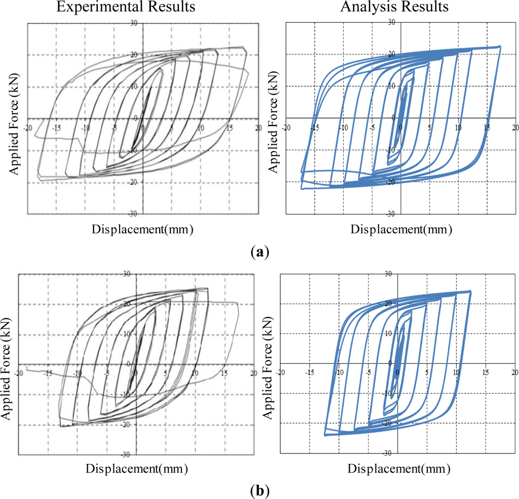
Ductility is important to achieve the inelastic zone and in inelastic energy dissipation. If the material is not ductile then it does not have the stamina to go into hundreds of inelastic cycles in case of an earthquake. These cycles look something like this:


The image above shows the force deformation relationship of a buckling restrained brace. These braces can work without failing in compression (buckling restrained) and so they can offer high strength as well as ductility in tension as well as compression. As you can see the area under the curve in the initial elastic zone which goes up to a displacement of 1 millimeter is very insignificant as compared to the rest of the area under the curve which shows that the braces can work up to 15 millimeters of displacement quite easily without losing its strength. This is the beauty of ductility. Apart from damping energy released the next maximum source of energy dissipation is the ductility in the lateral force resisting system. The energy dissipated in the form of these inelastic hysteresis loops is generally of the order of 15-30% of the strain energy itself. That is significant source of energy dissipation just by making sure that the structure is ductile enough. Isn't that pretty amazing? 

What are the members that contribute to these ductile energy dissipation?

1. Shear wall base or more commonly known as shear wall hinge zone. 
2. Coupling beams in coupled shear walls
3. Beams in a moment frame
4. Buckling restrained braces in case of a braced frame system
5. Conventional braces in case of a braced frame system
6. Link beams in case of eccentric braced frame system 

How to make sure that the structure is ductile? Oh boy, it is a vast topic. I am planning to put a next blog post soon which will be related to "Ductile design of structure in seismic zone". 

I hope you enjoyed a little introduction to what happens to a building during an earthquake and how energy is pumped into the building and how building works to dissipate that energy. Remember this was a very generalized post so do not take the numbers seriously. Make sure you do your research specific to your project because all the projects are different in case of structural engineering.


by ;  http://www.thestructuralmadness.com

martes, 7 de febrero de 2017

Ductility in Structures

Have you ever participated in a marathon? Or have you ever practiced for one? The only way you can finish a marathon is high stamina and a constant comfortable pace. If you run too fast, the energy in your body will drain out quickly and you will get tired within first 10% of the run. But if you maintain your own comfortable speed, where you heart beat is not too high then you could finish the marathon without even getting too tired. The key is glycogen stored in the body. On an average a person can store up to 2000 calories of energy that is readily available and then once this glycogen is consumed body starts burning fats to get energy which leads to fatigue. The key in marathon is to consume this glycogen efficiently and so you have to run at a comfortable pace. 
Similar to this concept, in structural engineering, a building has to perform under large forces without breaking itself to pieces. As we discussed about different sources of energy dissipation, we understood how inelastic energy dissipation plays an important role in resisting earthquakes. (The term earthquake resistant structures should be used in place of earthquake proof ). 
Inelasticity in materials generate large strains and large strains corresponds to larger deformations. Now how does a material look under large strains? Take a plastic bag and pull it as hard as you can. After a certain magnitude of force, the bag will stretch freely even if you don't increase the load. Thus you know that the material is already yielded and it has reached into its plastic state. Once you release the force, bag is not going back to its original shape but instead it will maintain its current deformed shape. This is called permanent deformation of the material. Similar to that if you take a mild steel rod and pull it under a universal testing machine, you will see that the steel rock necks down after a certain force, this is also a type of permanent deformation. Now before reading any further, if you have not then please do refer to our blog Ductility vs Elasticity and then continue reading this article.
Now as we discussed in the previous blog of Earthquake vs Energy Dissipation we talked about how elastic deformations of material result in very low energy dissipation while the inelastic zone of the stress strain curve helps in much more dissipation of energy. Inelasticity results in very high strains and so it is important that the member is ductile, why? Because ductility is the ability of the material to go under large strains means a material that is more ductile can go into inelastic zones and can dissipate a lot of energy. This means that a glass or plain concrete can shatter easily in an earthquake when loaded while steel can stretch itself and keep you safe.
Now how to make sure that we are achieving sufficient ductility for the structure? How do we make sure that the structure has enough reserves that it will not collapse? So here is the answer, the ductility of the structure is hidden inside its detailing. A well detailed structure will lead to a better performance under earthquakes as compared to a poorly detailed one. Structures are generally made of 2 primary materials concrete and steel. Now we all know that steel is a very ductile material, but concrete? Oh man, concrete is terrible in terms of ductility, it has hardly any tension capacity and it gets crushed in compression. So what to do?
We make concrete structures ductile by adding sufficient steel into concrete members, we make steel structures more ductile by making connection stronger than the member itself. We make a structure more ductile by making columns stronger than beams so that columns remain elastic in case of earthquakes. So it is not just one region where you focus on ductile detailing, but in fact it is present in a well designed and laid out structures. Let us pick one point at a time.
1. Shear capacity of beams
Let us go back to the structural mechanics class. We always learnt how shear demand is proportional to the pure moment demand acting in the beam. If moment demand is more, then it directly implied high shear demands. In case of moment frame beams or coupling beams (What is Coupling beam?) in shear walls, we make sure that the shear strength of beam is greater than the moment capacity of the member. How can we do that? Well, you put in reinforcement in the beam which gives you the positive and negative moment capacities of the beam. In case of lateral force resisting members, generally the positive and negative moment capacity of the beam is the same. Why is that? Because earthquake shakes the building back and forth and at one point if end 1 of the beam is experiencing positive moments then at the other instant it will experience negative moments when earthquake changes its direction of shaking. Refer to the video of test performed in a laboratory.
Image describing differential movement of coupling beams
Now the two ends of the beam have moment capacities and we know that if the force demand is greater than the capacities of the beam, then they will go into nonlinear state or plastic state and start rotating. This is only possible if sufficient shear capacity of the beam is generated. If the positive and negative capacity of the beam moment is sayMpr, then the shear demand in the beam (Vpr) will be equal to Vpr = 2Mpr/L. This will give us the maximum possible shear demand in the beam. If we have shear stirrups provided in the beam to match this demand, the the beam will not fail in shear which means we eliminated the shear failure of the beam. The only thing beam has to do is resist the moments and if the forces are greater than the capacity then they will start rotate and dissipate more and more inelastic energy and perform better in earthquakes. When you plot the loops of rotation vs force demand, it will look something like this:
2. Making columns stronger than beams and providing tight confinement
What is a framed structure? We consider beams and columns fixity of different types. But we make sure that the system does not become a mechanism and looses its stability. We make sure that there no significant plastic hinge formations or else structure will lose its stability and on a pushover curve the structure will lest with negligible stiffness and stability.
We design the frames to behave like this:
So that it resists the moments and shear forces acting in the building. Now earthquake also demands ductility, so we want the beams to go into nonlinear zone and rotate back and forth so that it can dissipate significant amount energy and it should look something like this:
So we want a ductile beam sway mechanism. In the above image it is shown in figure (b). Now let us talk about a concept first. Take two scales, one made of wood and other made of plastic. Try bending both the scales and see which one is easier to bend? Of course the thin plastic one. After that, put both the scales on top of one another and try bending them together. Feel this, do you even feel the presence of plastic scale while bending? Of course not, because it is so much more flexible and weaker than the wooden scale. Similarly, if we want to make sure that we get ductile sway mechanism, we have to make sure that column is not only stronger than beam in terms of moment of inertia, but also the joint of the beam and column is stronger than beam itself. This will give more stability to the structure.
A non ductile column sway mechanism creates moment hinges in the column and because the column is also loaded with gravity axial loads, it reduces the ductility and softens the building even further. This also creates permanent deformations in the building just like it is present in the picture. Also you can see that non of the beams have formed plastic hinges. Instead all the columns have these plastic hinges at the top and bottom of the structure. Now this significantly reduces the capacity of the building and if you plot a pushover curve of such structure it would look something like image (d) in the picture above. There is no ductility in the system which is really bad for earthquake resistance.

Think about earthquake as a constant flow of water into your mouth. If you are not able to drink the water at the same rater as it is entering into your mouth, then you will spill it and also will create a mess. Earthquake acts as the same way. It constantly pumps energy into the system and if the system is not able to dissipate the energy then it collapses.
We know that during lateral forces and because of interstory drifts columns experience maximum moments at the top and bottom of the story. Now we cannot lap the bars into the joint as those are the locations of maximum stresses. So the best possible location is around 5 ft from story height. This way, when the floor below is constructed the workers can easily stand on the floor and work on the column without worrying about the formwork and heights. Thus the construction process is accelerated.
There is one more reason of providing closely spaced ties in the end zones of columns. It is because of these splices the strength of the section gets slightly reduced and the ductility is also reduced. So to increase ductility and column confinement we have to provide smaller spacing of ties. 

In case of Moment frames reinforcement should be spliced at the middle height of the column as moment frame is LFRS system and it will experience very high moments. So the splicing is particularly shifted to middle height in moment frames. No matter how high is the story height it should be in the center of the column as it is a region of zero moment.
3. Shear wall confinement

Whenever shear wall experiences heavy moments, its extreme ends go under heavy compression as well as tension. In order to make sure that concrete remains confined and bars do not buckle, we provide closely spaced ties within a certain depth of the wall. As we provide closely spaced ties, we eliminate the risk of reinforcement buckling as well as keeping the concrete confined. Thus the ductility of shear wall is achieved. 
I hope this was a healthy discussion related to ductility in building. This was again just an introduction. In order to completely understand structural behavior, it is important to understand elastic and inelastic behavior of structures, softening of a structure, nonlinear analysis, cracking of concrete. Make sure you read enough books after reading this introduction so that you can relate to our explanation.
Our next blog will be ductility factor for different buildings. This factor is also known as response reduction factor for seismic analysis of structure.


by:http://www.thestructuralmadness.com

domingo, 22 de enero de 2017

How to check if a connection between steel members is a hinge

In the first workshop for students in WrUT organized by Enterfea and Dlubal, problem of rigidity of the connections in steel structures was presented and discussed. I had a pleasure to teach there with Ola Kociołek (CEO of Dlubal Poland).
Have you ever wondered how to be sure that your connection is a hinge? Perhaps you are interested in the influence of connections rigidity on the outcomes of static calculation or how to incorporate this rigidity in the design. Maybe you want to know when connection rigidity it is actually important and cannot be omitted…  you are in the right place!

Introduction

Topic of connections rigidity in steel structures became popular several years ago with the publication of code EN 1993-1-8. Chapter 5 of this code classified connections between steel members not only as hinges and rigid connections but also as semi-rigid. This alone was nothing new, but the fact that the code actually gave information on how to calculate this semi-rigid approach meant that this will be a “thing”. I won’t go to the procedure of calculation given in the code (I’m not a fan), but I will gladly discuss the phenomenon and give my advice, so everything here is not code-related and can simply be used regardless of codes you are using.
This is a very broad topic, so I decided to break it down into several posts. Today I will discuss verification if the connection is a hinge or not, but in upcoming weeks following topics will be discussed:
Main issues with connection rigidity:
  • How can I be sure that my connection is a hinge?
  • If my connection is semi-rigid how to calculate it’s rigidity?
  • How to take connection rigidity into account in static design?
  • How to know if connection rigidity is important in my design?

What a hinge really is

There is a misconception that a hinge is a connection that have no capacity to carry any significant bending moment. Unfortunately that is not true. Imagine a cantilever made of glass (that cannot carry any tension, and thus cannot carry any bending). If you would load such a cantilever then it would break (since it cannot carry any bending moment)… I wouldn’t call that a hinge.
aa2

To move examples to more “structural” area, lets take a beam like the one above. Assuming someone wished to treat this connection as a hinge, screws are placed wrongly. Since they weren’t designed for it, lets say those screws don’t have any significant capacity to carry tension. Notice that uplift deformations at the end of the beam will cause high tensile force in screws – this is nothing else than the beam trying to “fix itself” into the support using the pair of forces (tension in screws, compression in bearing). Screws do not have sufficient tensile capacity, so they break (and hence “allow” for rotation in the support).
This leads to a very important conclusion:
Hinges are connections that allow for free rotation.
It doesn’t matter if the connection capacity due to bending is high or low – if it allows for free rotation you simply cannot apply bending to it! Deformation of the structure increases (and other elements have to deal with the strain) but connection did not take any bending, so it’s capacity to it is irrelevant.
In the beam example above the screws prohibited rotation, so the connection took in the bending moment, and since screws capacity was small, they broke. If you would place screws like on the drawing below, those would not prohibit rotation. Such solution is a true hinge. Of course there is a “price” – since we do not carry bending “elsewhere”, analyzed beam will get much higher bending moment (but elements that are connected to the beam won’t get any, and that is the point!)
aa3

How to check if a connection is a hinge

So let’s think how to analyze if our connection allows for free rotation. Let’s use one of the most common shear connections as an example.
aa4
First of all we can notice, that with more than one screw the “free rotation” of our connection will be somehow limited. Since 2 screws can generate a pair of forces they can “try” to stop the rotation (by shear action). If any significant bending moment will be applied to this connection, it is obvious that the screws will break. Its because the distance between them is small, so the forces in the pair of forces will be very big.
However one can realize that the holes in all screwed connections have holes diameter higher than diameter of the screw. Taking this into account shows that in order to carry shear (in a non-preloaded connection) screws have to “travel” to the edge of the hole first (see below). This distance is relatively small (usually 0.5-1.5mm depending on the screw size and it’s location in the hole), but with a distance between screws being small as well, this actually produces a quite significant rotation possibility (especially since rotations in typical beams are quite small).
aa5So the easiest method to verify if the connection is a real hinge is to check what is the allowable free rotation, and then apply hinge in static design and see if the rotation in that connection is smaller than the allowable free rotation. If it is – connection is a hinge.
When the rotation is actually higher (which in most cases mean you are calculation something interesting), then this will be a bit more tricky. I will get to this in the next post (using the numerical model shown above). If you are interested in it, be sure to subscribe so you won’t miss it 🙂
Also not all cases allow to estimate the free rotation in hand calculations. Sometimes you have to do a simple numerical study to see what the allowable rotation is – eventually I will get to this as well.
by: http://enterfea.com/

sábado, 14 de enero de 2017

Sismo Italia

An earthquake of magnitude 6.6 struck the center part of Italy (6 km from Norcia) for the second time since earthquake in Aug 2016. The earthquake is believed to be the strongest to hit Italy since 1800. But why is Italy so prone to earthquake? In this brief note, we will review some facts about the seismic activity in the region, the existing codes, and practice, and why collapse of buildings is common in Italy.

Why So Many Earthquakes in Italy?

The constant movement of tectonic plates is one reason for having so many earthquakes in Italy. The movement of Euarasian and African plates against each other creates seismic activity and volcanic tension. Presence of major and minor faults along the Appenine Mountains is also contributing the high seismic activity of the region. This Apernine range runs from north to south of the country, and shallow depth earthquake happening along this range is very common. This all creates a very complex tectonic movement.

Seismic Risk in Italy

According to the seismic hazard risk, Italy has a medium-to-high seismic hazard. The population density and its ancient historic sites, as well as high exposure, makes Italy extremely vulnerable. Italy has 4 major sesimic hazard zone, with zone 1 having the highest seismic activity, and zone 4 having the least risk.
Seismic map Italy
Image source: http://www.protezionecivile.gov.it/jcms/en/classificazione.wp

Why so many buildings collapse?

Italy is an ancient country, with construction dating back to 2-3 thousand years. While major cities like Roma, Milan, or Turin are very industrialized over the past decades, smaller cities and villages have not seen much improvements or upgrade to their residential or historic sites. The collapse of the centuries old Basilica of San Benedict in Norcia is one famous example.
Earthquakes in Italy basilica-norcia-1000x561
Image Source: http://www.nbcnews.com/news/world/beer-brewing-monks-norcia-say-earthquake-destroys-st-benedict-basilica-n675536
unreinforced masonry construction is a common observation in the damaged sites. While retrofit and upgrade techniques such as the concrete jacketing or carbon fiber strengthening is widely used for relatively old construction, the use of these techniques on very old structures have not yet studies very well. On another note, it is entirely up to the owner to upgrade a residential building. Unlike buildings and facilities that are owned by government or other large private organizations, the owners of residential buildings are not obliged to implement such upgrades. the huge cost of reconstruction and upgrade is another big challenge.

How About Modern Construction?

With all being said about very old construction, let’s look into the condition of newer construction in Italy. “Modern construction will take seismic hazard assessment into account and I expect new buildings will be built according to modern standards,” says De Angelis.  In fact, Italy has one of the most advanced building codes for new constructions, state-of-the-art in the field. The very famous ROSE school is one of the leading research centers in this area.

Concluding Remarks

In this note, we learnt that Italy is located in a region of medium to high seismic activity. The large population of the country, as well as the old cities and villages, make Italy extremely vulnerable. While seismic provisions in modern design and construction codes are implemented, the challenge is to accurately assess the seismic safety of existing buildings, and prioritize interventions for retrofit and seismic upgrade. Development of innovative retrofit techniques, and new materials for seismic upgrading of existing masonry construction can offer a lot for the constant problems we see after each earthquake in Italy.